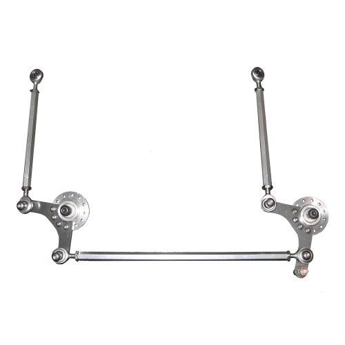

Parametric design charts are proposed for the central-lever steering linkage, generated for simplified reference configuration mechanisms, the geometry of which is defined by only four parameters. This highlights the fact, yet not generally acknowledged, that the steering law ensured by a mechanism with adjacent central joints (known as bell crank mechanism), can be identically generated by a triple central joint variant of the same. Microsoft flight simulator 2020 for mac os. Particular configurations are identified in which the length of the central lever does not affect the wheel-to-wheel transmission function of the mechanism, permitting a simplified synthesis for the cases in which the maximum stroke of the input member is imposed as a design specification.
Design Of Bell Crank Lever Action
Complete the work. The bell crank lever is an apparatus shown in Figure-1 which is used to verify the law of moments. Mac os x pages export to html. The bell crank apparatus is capable for changing the direction of rotation. It is a type of crank which changes motion around a 90 degree angle. The free body diagram of the bell crank apparatus is shown in Figure-2. Learn and revise mechanical devices with BBC Bitesize for GCSE Design and Technology AQA. Bell crank linkages change the direction of force through 90°. It is important when using levers. Handlebar lever is rotated at an angle of 90. To push the brake block against the wheel rim 2 Figure 1: Typical example of a bell crank 2 2.0 Initial Load Case. Figure 2: CAD Model of In-line Bell crank thus the results are taken to be as Figure 2 shows the design of the in-line bell crank. Mega man 11 pc gameplay. The bell crank is expected to be made of steel.